FINS - Factory Interface Network Service
The FINS Driver is used to communicate with Omron PLCs. The driver can be used for messages or as I/O polling.
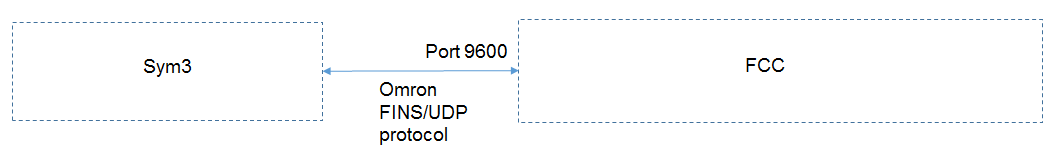
The PLC and Sym3 are connected via FINS/UDP protocol and exchange I/O.
The driver supports DM (Data memory) and EM (Extended memory) where EM is the preferred option. The driver only supports 16 bit WORD read and writes.
For full details of FINS addressing refer to the OMRON FINS protocol and the PLC manual.
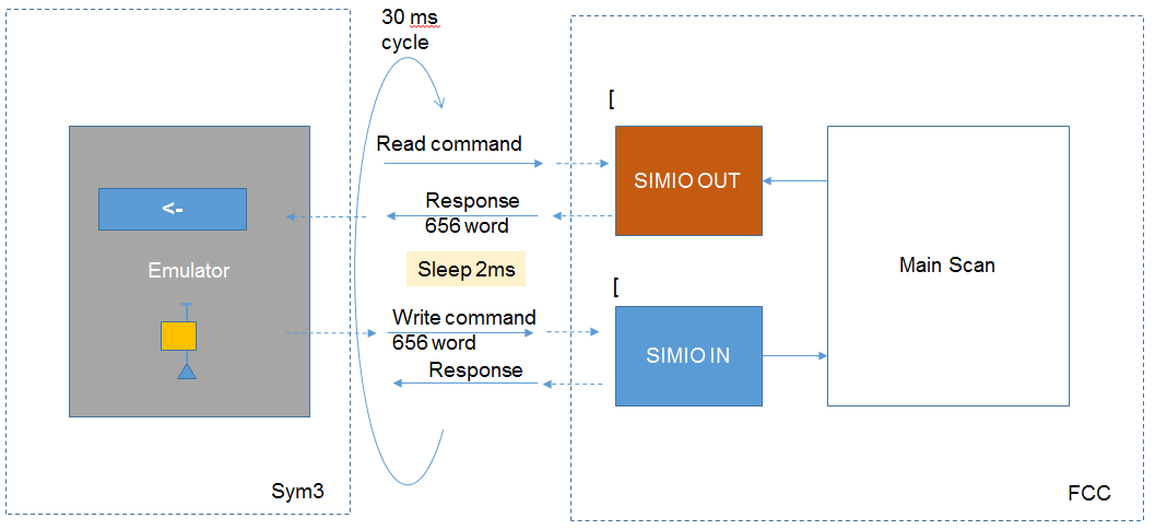
As shown below, memory Read command and memory Write command are issued and I/O is exchanged.
Example:
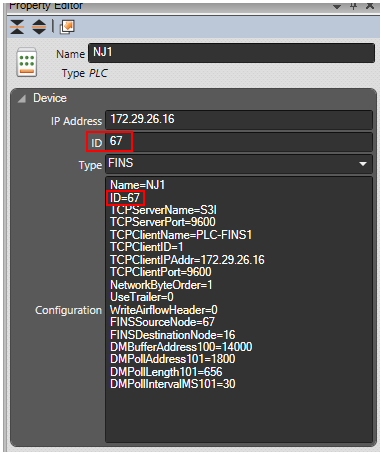
The following is an example of the configuration for a 'FINS' type:
| Name | Description |
| Name | Can be anything. This name will appear in the Sym3 log files |
| ID | Must be the same as ID field and unique across all Sym3 'PLCs' |
| TCPServerName | Server name as used in Sym3 log file. Can be up to 16 ASCII characters. |
| TCPServerPort | Port that Sym3 listens on. Must the same as the TCPClientPort (see below) |
| TCPClientName | Client name as used in Sym3 log file. Can be up to 16 ASCII characters. |
| TCPClientID | Sym3 constant. Must be Set to 1 |
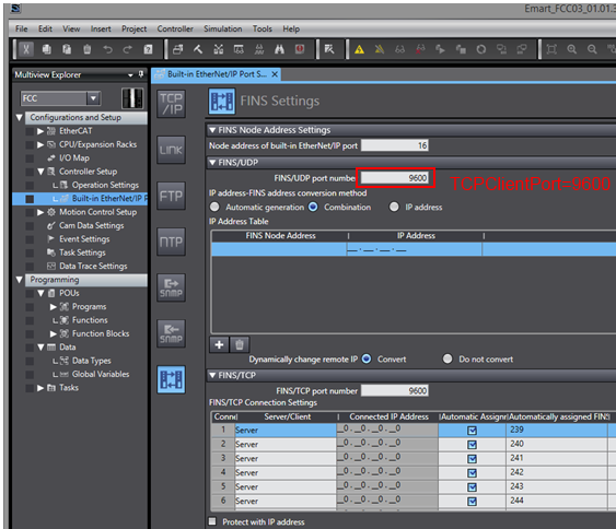
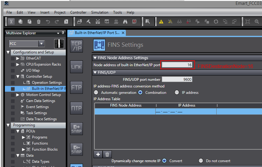
| TCPClientIPAddr | IP Address of the PLC as set in Sysmac TCP/IP Settings Must match the IP address Field in Sym3 PLC properties. |
| TCPClientPort | Port that the PLC is listening on. Must match the Sysmac FINS/UDP port number in FINS Settings |
| NetworkByteOrder | Must be 1 |
| UseTrailer | Must be 0 (zero) |
| WriteAirflowHeader | Must be Set to 0 (zero) |
| FINSSourceNode | The FINS Header Source node. Must be the last octet (byte) of the PC (Sym3 Integrator) IP address. In the example set up this is 67. Only required if Omron PLC sends messages (instruction 090). |
| FINSSourceNetwork | The Network number of the machine running Sym3 Integrator. Typically 0 (zero). |
| FINSDestinationNode | The FINS Header destination node. Must be the last octet (byte) of the PLC IP address. 16 in the sample setup with the PLC IP 172.29.26.16. It must match the FINS send destination Node number |
| FINSDestinationNetwork | The Network number of IP address of the PLC. Typically 0 (zero). |
| DMBufferAddress100 | The Data Memory I/O address (14000) used for Sym3 PLC Device IO message 100 (PLC input). This issues a FINS Data Memory write command 0x0102 to the PLC. The length field in the command is determined by size of the Sym3 PLC Device IO map. |
| DMPollAddress101 | The Data Memory I/O address (1800) used for Sym3 PLC Device IO message 101 (PLC output). This issues a FINS Data Memory read command (0x0101) to the PLC. |
| DMPollLength101 | The length field in words (656) sent in the Data Memory read command for message 101 |
| DMPollIntervalMS101 | The interval in milliseconds that FINS Data Memory read command is sent to the PLC. |
| DMBufferIntervalMS100 | The interval in milliseconds that FINS Output data is sent to the PLC. |
| ContinuouslySendingOutput | The boolean flag to enable continues sending output data to the PLC, when set to true DMBufferIntervalMS100 will be used as interval to send FINS output data to the PLC. When false Output data will only be send to PLC when updated. |
Extended Memory parameters (from Sym3 V5.2 on)
| Property | Description |
| IOMemoryAreaCode100 | Specify the FINS I/O Memory Area Code for the message numbers used in Sym3 Device I/O and messaging |
| IOMemoryAddress100 | The EM Memory I/O address (14000) used for Sym3 PLC Device IO message 100 (PLC input). This issues a FINS Data Memory write command 0x0102 to the PLC. The length field in the command is determined by size of the S3I PLC Device IO map. |
| IOMemoryPollAddress100 | The memory address for the message numbers used in Sym3 Device I/O and messaging |
| IOMemoryPollLength100 | The Length in WORDs to read from the Memory Area address in the PLC for the message numbers used in Sym3 Device I/O and messaging |
| IOMemoryPollIntervalMS100 | The time between Memory Area reads in milliseconds for the message numbers used in Sym3 Device I/O and messaging |
When using Extended Memory space the DMBufferAddress and DMPollAddress syntax can still be used with I/O Memory Area Code automatically being set to Data I/O Memory (0x82).
DMBufferAddress123=1000
is equivalent to;
IOMemoryAreaCode123=0x82
IOMemoryAddress123=1000
Summary of the new EM commands are;
FINS I/O Memory Area Write (0x0102)
IOMemoryAreaCodeXXX=0xMM
IOMemoryAddressXXX=AAAAA
FINS I/O Memory Area Read (0x0101)
IOMemoryAreaCodeYYY=0xMM
IOMemoryPollAddressYYY=AAAAA
IOMemoryPollLengthYYY=L
IOMemoryPollIntervalMSYYY=T
Where:
XXX and YYY are the message numbers used in Sym3 Device I/O and messaging.
MM is the FINS I/O Memory Area Code. See W342-E1-15.pdf 5-2-2 IO Memory Address Designations. Common values: Data I/O Memory is 0x82, Extended I/O Memory for CS/CJ processors for EM bank 0 to bank F is 0xA0 to 0xAF.
AAAAA is the Memory Area address being written or read.
L is the Length in WORDs to read from the Memory Area address in the PLC.
T is the time between Memory Area reads in milliseconds.
Example
Name=PLC1
ID=67
TCPServerName=S3i
TCPServerPort=9600
TCPClientName=PLC-FINS1
TCPClientID=1
TCPClientIPAddr=172.29.26.16
TCPClientPort=9600
NetworkByteOrder=1
UseTrailer=0
WriteAirflowHeader=0
FINSSourceNode=67
FINSSourceNetwork=0
FINSDestinationNode=16
FINSDestinationNetwork=0
DMBufferAddress100=14000
Adding the following entries to the configuration changes the communications method from messaging to polling. The driver does not change.
DMPollAddress101=1800
DMPollLength101=656
DMPollIntervalMS101=30
With Polling mode, the results are returned in message number 101.
Adding the following entries to the configuration changes the output sending method from on update to continues. The driver does not change.
ContinuouslySendingOutput=True
DMBufferIntervalMS100=1000
With Continues mode, the data send to PLC will be message number 100.
Configuration screens
Example Sym3 projects using this driver.
These are simple examples including conveyors and PEs to demonstrate the setup and principles of operation
Sym3-NJ1-FINS.s3i - Example project (messaging)
Sym3-NJ1-FINS-Polling.s3i - Example project (polling)
PLC-NJ1-FINS.smc2 - Example PLC code